Smart Clock Course
Item Checklist
Make sure you have all these item before starting making
| Items | Quantity |
|---|---|
| 7 Segment Module | 4 |
| ESP32 Devkit V1 | 1 |
| BC337 | 5 |
| Switches | 3 |
| Potentiometer | 1 |
| LDR | 1 |
| 1N4001 | 1 |
| Terminal Block 2pin | 1 |
| Terminal Block 3pin | 1 |
| Relay | 1 |
| DC barrel jack | 1 |
| LED 5 mm | 1 |
| XD2803 | 1 |
| 18pin IC holder | 1 |
| 10k resistor | 13 |
| 470ohm resistor | 2 |
| 140ohm resistor | 8 |
| BMP180 | 1 |
Start by soldering
Tips for soldering is to solder all the small shorter stuff first then only solder bigger larger item such as relay or pinheader. Also make sure to use a good soldering iron and solder. I recommend using a soldering iron with a temperature of 350-400 degrees celcius and a solder with a melting point of 183-217 degrees celcius.
Check Soldering
After soldering you are advised to check for short circuit or wrong placement. You can use multimeter to check for short circuit. You can use a multimeter to check for wrong placement. You can also use a multimeter to check for continuity. If you have a multimeter you can check for continuity by connecting the positive and negative probe to the same pin. If the multimeter shows a value then there is a short circuit. If the multimeter shows 0 ohm then there is no short circuit.
Plug In ESP32 and upload example program.
- Go to Online Upload Tools If everything is working you will see
Setup Computer to rewrite program for ESP32
Visual Studio Code and PlatformIO Plugin
Visual Studio Code Steps to install PlatformIO
- Open VSCode Package Manager
- Search for the official
platformio ideextension - Install PlatformIO IDE.
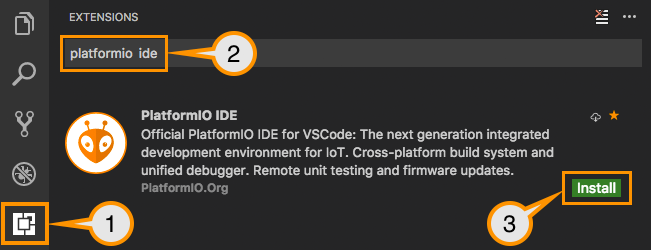
- Wait For PIO to be installed then restart Visual Studio Code
Setting Up Projects
- Press on this
 on left side bar then press Open or home icon to Open PIO home
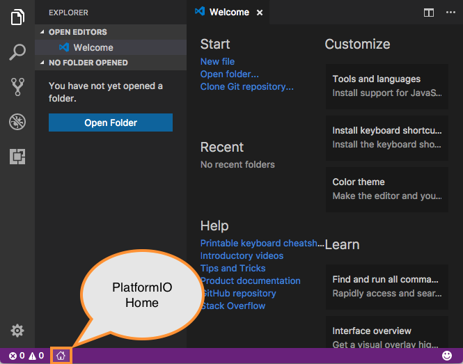
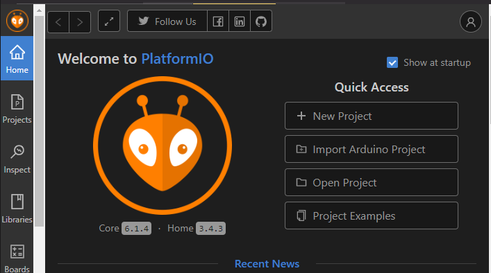
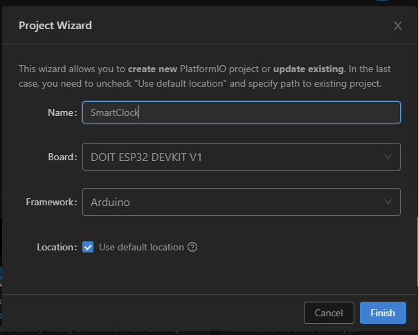
- Click on “New Project”, select a board and create new PlatformIO Project
- Add Name then Board select DOIT ESP32 DEVKIT V1
- Open
main.cppfile fromsrcfolder and replace its contents with the next:
/**
 * Blink
 *
 * Turns on an LED on for one second,
 * then off for one second, repeatedly.
 */
#include "Arduino.h"

// Set LED_BUILTIN if it is not defined by Arduino framework
// #define LED_BUILTIN 13

void setup()
{
  // initialize LED digital pin as an output.
  Serial.begin(115200);
  pinMode(LED_BUILTIN, OUTPUT);
}
void loop()
{
  // turn the LED on (HIGH is the voltage level)
  digitalWrite(LED_BUILTIN, HIGH);
  Serial.println("LED ON");
  // wait for a second
  delay(1000);

  // turn the LED off by making the voltage LOW
  digitalWrite(LED_BUILTIN, LOW);
  Serial.println("LED OFF");
   // wait for a second
  delay(1000);
}
Build then upload your project using
ctrl+shift+Pthen typeupload or
or buildto build. Or use use this toolbar.
PlatformIO: Build
PlatformIO: Upload
PlatformIO: Clean
Project environment switcher (if more than one environment is available). See Section [env] of “platformio.ini” (Project Configuration File).
After Upload You Should See Led Blinking.
Now We Are Going To Learn Some Basic Function For Arduino
if you are pro feel free to skip this step to here
Serial
Serial.begin and Serial.print
Serial.begin(x) Open the serial port at x bps, if you are using esp32 it is advisable that you use 115200bps as it is the default speed to see boot information.
Serial.println("LED ON"); Will printout "LED ON" on Serial Monitor.
Serial.print(); Will printout word without \n(nextline).
pinMode
pinMode(LED_BUILTIN, OUTPUT); this will set LED_BUILTIN pin to OUTPUT. LED_BUILTIN is defined by arduino library, You can change to other pin to set other pin. Second column OUTPUT can be INPUT or INPUT_PULLUP
pinMode(13,OUTPUT); This will set pin13 to OUTPUT;
digitalWrite
digitalWrite(LED_BUILTIN, HIGH); This will set LED_BUILTIN pin to HIGH. for this example it will set LED_BUILTIN to 3.3V so LED will light up.
HIGH = 3.3V at esp32
LOW = 0V
digitalWrite(LED_BUILTIN,LOW); This will set the pin to 0V thus closing LED.
delay
delay(1000); Will delay the whole code for 1000ms = 1s You can change it to 1 for 1ms or 1000 for 1s
delayMicroseconds(us) Delay but with microsecond input;
Now Let's Play with Seven Segment (Part 1)
First Lets Watch the Seven Segment Connection

As you can see here there are pin that control segment led and one that control which segment
| 7segCOM | 7segCOM1-4 |
|---|---|
 |  |
if you search internet for 7segment you will know a - g and dp is mapped like this
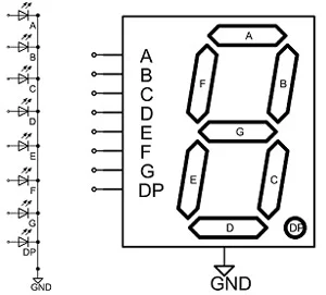
As you can see the image shown here all segment is actually a led incase you still don't know. So to control 7segment is easy you just need to turn on pinA for A to light up.
So as you have already learn from here and here you can light up any number you want just set the pin to HIGH.
Now that your task is to light up 7 at your 1st segment.
Hmmm It didn't light up ???
You most likely forgot something here need to set HIGH to light up the 1st segment.
If It light up !!!
Now try light up different segment with different number all showing together not just single segment. if You Need Help only, brainless ppl only press this btw
Now Let's Play with Seven Segment (Part 2)
Now you know that we can light up 7segment with different number and different segment. Now we are going to learn how to light up 7segment while still running our code. To know how to multitask we first have to go back to blinking led example. but before this we need to learn afew more arduino function.
millis
millis() calling this function will return(give you) the number of milliseconds since the program started. The function will return a 32 bit unsigned integer. The maximum value is 4294967295 (2^32-1). The value will be reset to 0 when the program restarts. This function is useful for timing purposes which we will use later.
From now on you might also need to know variable data type.
Please Click Here if you dunno what is data type, feel free to skip if you know already
So now we are going to do a simple code that will blink two led at different time. For now we are going to use the two led middle of the 4 segment.
Please use Schematic to find to pin for the led.
#include <Arduino.h>

int led1 =
int led2 =
unsigned long previousMillis = 0;
unsigned long interval = 1000;
uint32_t interval2 = 500;

void setup() {
  pinMode(led1, OUTPUT);
  pinMode(led2, OUTPUT);
}

void loop() {
  unsigned long currentMillis = millis();
  if(currentMillis - previousMillis >= interval){
    previousMillis = currentMillis;
    digitalWrite(led1, !digitalRead(led1));
  }
  if(currentMillis - previousMillis >= interval2){
    previousMillis = currentMillis;
    digitalWrite(led2, !digitalRead(led2));
  }
}
Now you should see two led blinking at different time. Led1 will blink every 1s and led2 will blink every 0.5s.
From here you can try to make your own code that will blink all 7segment without using delay.
Please do not use delay for this task. After you finish this task you can go to Part3.
Now Let's Play with Seven Segment (Part 3)
Now we gonna use esp32 only function to make our code more efficient and easier to use and program. Please remember these function is esp32 only so if you are using other board you can't use it.
So we are going to introduce you to FreeRTOS. this is a real time operating system that will help you to multitask your code which is included in esp32.
It is recommended that you watch all video in this playlist to understand how to use FreeRTOS.
If you think my skill of writing docs sucks just watch that playlist ^^ youtube video is better than watching words right ? if you seen all video in this playlist you can skip this part to Part3Task
Part 3 Task
This task you are required to do is to make your code that will show random 4 digit number on 7segments then change it at every 1 second.
Now Let's Get Our ESP32 Connected to the Internet and take time from NTP Server
As usual we are going to learn a few more arduino function.
First you need to include WiFi.h library. To use WiFi
#include <WiFi.h>
From here we can use some function from WiFi.h library.
WiFi.begin(ssid, password)
WiFi.begin(ssid, password);
This function will start the wifi connection. ssid is the name of the wifi and password is the password of the wifi.
WiFi.status()
WiFi.status();
This function will return the status of the wifi connection. You can use this to wait for the wifi connection to be established. By doing
while(WiFi.status() != WL_CONNECTED){
  delay(500);
  Serial.print(".");
}
After this ESP32 will be connected to the internet.
WiFi.localIP()
WiFi.localIP();
This function will return the local IP of the ESP32.
WiFi.hostname(hostname)
WiFi.hostname(hostname);
This function will set the hostname of the ESP32.
WiFi.macAddress()
WiFi.macAddress();
This function will return the mac address of the ESP32.
WiFi.disconnect()
WiFi.disconnect();
This function will disconnect the ESP32 from the internet.
For more detailed information about WiFi please visit here.
Now we need to take time from NTP Server.
Here are some function that we use to take time from NTP Server.
configTime()
configTime(gmtOffset_sec, daylightOffset_sec, ntpServer1);
gmtOffset_sec is the time difference between your time zone and UTC time. For example if your time zone is UTC+8 then gmtOffset_sec is 8*3600 = 28800. DataType is long/int32_t
daylightOffset_sec is the time difference between your time zone and UTC time during daylight saving time. For example if your time zone is UTC+8 then daylightOffset_sec is 0. DataType is int.
ntpServer1 is the NTP server that we will use to take time from. For example ntpServer1 can be "pool.ntp.org". DataType is char*.
All of these variable can be set as const. And this configTime() only need to be run once.
getLocalTime()
getLocalTime(&timeinfo);
This function will set local time into the timeinfo variable. tm(timeinfo) is a struct that contains all the time information.
If getLocalTime fail then it will return false else it will return true. So you can use this function to check if getLocalTime() is success or not by doing
if(getLocalTime(&timeinfo)){
  Serial.println("Got time");
}else{
  Serial.println("Failed to get time");
}
You should also create a struct tm(timeinfo) before using this function.
struct tm timeinfo;
After you use getLocalTime you can You can access the date & time information by accessing members of this time structure.
| %A | returns day of week |
| %B | returns month |
| %d | returns day of month |
| %Y | returns year |
| %H | returns hour |
| %M | returns minute |
| %S | returns second |
Serial.print("Current time: ");
Serial.println(&timeinfo, "%A, %B %d %Y %H:%M:%S");
strftime()
strftime(buffer, sizeof(buffer), "%A, %B %d %Y %H:%M:%S", &timeinfo);
buffer is the buffer that we will use to store the time. DataType is char*.
This function will set the date & time into the buffer. buffer is the buffer that we will use to set the date & time. sizeof(buffer) is the size of the buffer.
You can go here to get more information about tm(timeinfo) struct with strftime. Here